This is part of a series on network virtualization, see Beyond VLANs, for links to all parts of this series.
We have explored the L2 aspects of virtualization with VLANs, SVIs and Subinterfaces, but what if we needed to virtualize things at a L3 layer. What if we needed a router to handle traffic for multiple customers or groups without allowing access between them. A traditional non-virtualized way to deal with this would be with ACLs between each of these groups, but this can become cumbersome to manage and a mistake in an ACL can cause a security issue. You could also tackle the separation of these group via virtualization using Virtual Routing and Forwarding (VRF). Technically I’ll be discussing VRF-Lite here, for info on full blown VRF see the upcoming post on L3 MPLS VPNs.
A device supporting VRF will have:
- A global routing table which is the default routing table, this exists if you are using VRF or not
- One or more VRFs
- Each interface on the device will belong to either the global routing table or one of the VRFs
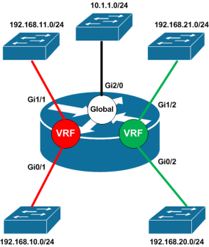
So for example say we have a red group and a green group which we want to keep separate. Each group has two switches that are all connected to a single router. The solution would look something like this.
Here we have a router with a Red and a Green VRF along with it’s global routing table. The Red VRF includes interfaces Gi0/1 and Gi1/1 connected to the switches for the red group and the Green VRF includes interfaces Gi0/2 and Gi1/2 connected to switches for the green group. Since each VRF is a separate routing table a system with the IP 192.168.10.10 in the Red VRF could not ping a system with the IP 192.168.20.10 in the Green VRF. The ping packets would simply be dropped by the router since the VRF that received the traffic (i.e. Red) does not have a route to the destination.
If we looked at the routing table for Red VRF it would look something like this:
Router# show ip route vrf Red
Codes: C - connected, S - static, R - RIP, M - mobile, B - BGP
       D - EIGRP, EX - EIGRP external, O - OSPF, IA - OSPF inter area
       N1 - OSPF NSSA external type 1, N2 - OSPF NSSA external type 2
       E1 - OSPF external type 1, E2 - OSPF external type 2, E - EGP
       i - IS-IS, su - IS-IS summary, L1 - IS-IS level-1, L2 - IS-IS level-2
       ia - IS-IS inter area, * - candidate default, U - per-user static route
       o - ODR, P - periodic downloaded static route

Gateway of last resort is not set

C    192.168.10.0/24 is directly connected, GigabitEthernet0/1
C    192.168.11.0/24 is directly connected, GigabitEthernet1/1
As you can see the only routes that exist in the Red VRF are for the two subnets for the red group. The green VRF looks the similar with just connected routes for the subnets for the green group.
The router also has a global table which act’s just like a VRF (it’s often refereed to as the Global VRF, but it’s technically not a VRF). The global routing table only includes routes that are not specifically included in another VRF and has no special visibility into the other VRFs. Here is the routing table of the global routing table.
Router# show ip route
Codes: C - connected, S - static, R - RIP, M - mobile, B - BGP
       D - EIGRP, EX - EIGRP external, O - OSPF, IA - OSPF inter area
       N1 - OSPF NSSA external type 1, N2 - OSPF NSSA external type 2
       E1 - OSPF external type 1, E2 - OSPF external type 2, E - EGP
       i - IS-IS, su - IS-IS summary, L1 - IS-IS level-1, L2 - IS-IS level-2
       ia - IS-IS inter area, * - candidate default, U - per-user static route
       o - ODR, P - periodic downloaded static route

Gateway of last resort is not set

C    10.1.1.0/24 is directly connected, GigabitEthernet2/0
If you only need to separate two groups, you could even just create a single VRF and have one group in the VRF and the other in the global table. In the example above the global table would likely be used for management.
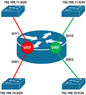
Another effect of keeping the routing tables of VRFs separate is that the same address space can be used in the different VRFs. For example it’s possible the same subnets could be used in both the Red and Green VRFs.
The routing tables for the VRFs would look like this, where connected routes for the same ip networks would show up on different interfaces.
Router# show ip route vrf Red
Codes: C - connected, S - static, R - RIP, M - mobile, B - BGP
       D - EIGRP, EX - EIGRP external, O - OSPF, IA - OSPF inter area
       N1 - OSPF NSSA external type 1, N2 - OSPF NSSA external type 2
       E1 - OSPF external type 1, E2 - OSPF external type 2, E - EGP
       i - IS-IS, su - IS-IS summary, L1 - IS-IS level-1, L2 - IS-IS level-2
       ia - IS-IS inter area, * - candidate default, U - per-user static route
       o - ODR, P - periodic downloaded static route

Gateway of last resort is not set

C    192.168.10.0/24 is directly connected, GigabitEthernet0/1
C    192.168.11.0/24 is directly connected, GigabitEthernet1/1

Router# show ip route vrf Green
Codes: C - connected, S - static, R - RIP, M - mobile, B - BGP
       D - EIGRP, EX - EIGRP external, O - OSPF, IA - OSPF inter area
       N1 - OSPF NSSA external type 1, N2 - OSPF NSSA external type 2
       E1 - OSPF external type 1, E2 - OSPF external type 2, E - EGP
       i - IS-IS, su - IS-IS summary, L1 - IS-IS level-1, L2 - IS-IS level-2
       ia - IS-IS inter area, * - candidate default, U - per-user static route
       o - ODR, P - periodic downloaded static route

Gateway of last resort is not set

C    192.168.10.0/24 is directly connected, GigabitEthernet0/2
C    192.168.11.0/24 is directly connected, GigabitEthernet1/2
Of course providing L3 separation on a single device maybe of limited use. Often you will want to segment different groups located in different buildings/offices and there maybe several routers in between those groups. One way to provide L3 separation over several L3 devices is with a Back-to-Back VRF configuration.
In the Back-to-Back VRF setup you have two or more L3 devices connected together where each one is configured with the VRFs needed to keep the routing separate.
In this case we have two routes connected together via a trunk. Each router has a Red and Green VRF where each VRF includes an interface connected to a switch and a subinterface connected to the other router over the trunk. This would allow a server with IP 192.168.10.10 to talk with a server with the IP 192.168.20.10 (both in the Red VRF), but neither could talk to a server with IP address 192.168.20.10 (in the Green VRF).
The routing tale of router1 would look like:
Router1# show ip route vrf Red
Codes: C - connected, S - static, R - RIP, M - mobile, B - BGP
       D - EIGRP, EX - EIGRP external, O - OSPF, IA - OSPF inter area
       N1 - OSPF NSSA external type 1, N2 - OSPF NSSA external type 2
       E1 - OSPF external type 1, E2 - OSPF external type 2, E - EGP
       i - IS-IS, su - IS-IS summary, L1 - IS-IS level-1, L2 - IS-IS level-2
       ia - IS-IS inter area, * - candidate default, U - per-user static route
       o - ODR, P - periodic downloaded static route

Gateway of last resort is not set

C    192.168.0.0/30 is directly connected, GigabitEthernet0/0.1
S    192.168.10.0/24 [1/0] via 192.168.0.2
C    192.168.11.0/24 is directly connected, GigabitEthernet0/1

Router# show ip route vrf Green
Codes: C - connected, S - static, R - RIP, M - mobile, B - BGP
       D - EIGRP, EX - EIGRP external, O - OSPF, IA - OSPF inter area
       N1 - OSPF NSSA external type 1, N2 - OSPF NSSA external type 2
       E1 - OSPF external type 1, E2 - OSPF external type 2, E - EGP
       i - IS-IS, su - IS-IS summary, L1 - IS-IS level-1, L2 - IS-IS level-2
       ia - IS-IS inter area, * - candidate default, U - per-user static route
       o - ODR, P - periodic downloaded static route

Gateway of last resort is not set

C    192.168.0.4/30 is directly connected, GigabitEthernet0/0.2
S    192.168.20.0/24 [1/0] via 192.168.0.6
C    192.168.21.0/24 is directly connected, GigabitEthernet0/2
Each VRF has it’s connected routes along with the static route to reach the network on the other router. While this example uses static routes, dynamic routing protocols can be used and would just form adjacencies with each other over their respective subinterfaces.
The problem with Back-to-Back VRF configurations is that each router in the path must be configured with the appropriate VRFs. In the next posts I’ll show how we can connect VRFs using Overlay networks or L3 MPLS VPNs which minimize the need of VRFs on transport devices.
This is part of a series on network virtualization, see Beyond VLANs, for links to all parts of this series.


[…] the previous part I discussed Layer 3 virtualization using a back-to-back VRF configuration to provide L3 isolation for the entire path. This works fine if your path is only a […]
Pingback by Network Virtualization: Beyond VLANs – Part 6: Overlay Networks « Infrastructure Adventures — 01/16/2011 @ 3:32 PM
[…] Back-to-Back VRF and Overlay networks, MPLS L3 VPNs provide L3 isolation to virtual networks hosted on a physical […]
Pingback by Network Virtualization: Beyond VLANs – Part 7: MPLS L3 VPNs « Infrastructure Adventures — 02/20/2011 @ 7:24 PM